
Why Relying on a Single Level Sensor in Storage Tanks Is a Critical Risk (And What to Do Instead)
The Illusion of Simplicity
A single-level sensor seems like the obvious, cost-effective solution—especially when tanks appear stable and operations run smoothly. But in industrial storage, apparent simplicity masks systemic vulnerability. One sensor failure doesn’t just mean missing data—it can trigger overfills, under-draws, safety incidents, environmental releases, or unplanned shutdowns.
3 Hard Truths Behind Single-Sensor Reliance
1. No Redundancy = No Fault Tolerance
Sensors degrade. Wiring corrodes. Electronics drift. Calibration drifts ±2–5% annually—even with maintenance. With one sensor, there’s no way to detect silent failure until it’s too late. You don’t know it’s wrong until it’s catastrophically wrong.
2. Technology Blind Spots Are Inevitable
- Radar fails with heavy foam, condensation, or agitated surfaces
- Ultrasonic misreads in high-dust, low-temperature, or vapor-rich environments
- Float switches jam, stick, or wear out mechanically
- Capacitance probes drift with changing product conductivity or coating buildup
One technology cannot adapt to all process conditions.
3. Regulatory & Insurance Requirements Are Escalating
ISO 26782, IEC 61511, and EPA Tier II reporting increasingly treat single-point level measurement as non-compliant for hazardous or high-volume storage. Insurers now flag single-sensor configurations during risk assessments—and may exclude coverage for incidents linked to undetected level failures.

Real Impact: What Happens When You Upgrade
- +92% reduction in overfill events (per Shell Global Operations benchmark, 2024)
- 4.3x faster incident detection (average time-to-alert drops from 18 min → <4 min)
- Compliance alignment with ISA-84, NFPA 30, and local fire codes
- Lower TCO: Fewer emergency interventions, less product loss, avoided fines & downtime
Actionable Next Steps (Start Today)
- Audit your critical tanks: Flag all vessels storing >10 m³ of flammable, toxic, or regulated substances
- Map existing sensors: Note technology type, age, calibration date, and isolation from power/control systems
- Apply the “Two-Plus-One” rule: At minimum, deploy two diverse continuous sensors + one independent high-level cutoff
- Validate logic—not just hardware: Ensure your DCS/PLC compares readings, calculates rate-of-change anomalies, and triggers alarms before setpoints are breached
Final Thought
Level measurement isn’t about reading a number—it’s about maintaining process integrity, personnel safety, and regulatory trust. A single sensor is a gamble. Layered assurance is an engineering discipline.
— Built for reliability. Designed for resilience. Measured with confidence.
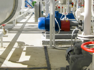 The Steel Joints of Coal Chemical Industry: A Complete Guide to How Valves & Instruments Govern the Entire Process Flow
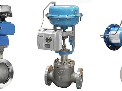 Why Are Valve Positioners So Important?
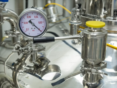 5 Common Causes of Inaccurate Level Gauge Readings and On-Site Troubleshooting Methods
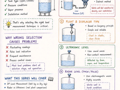 Differential Pressure Level Transmitter: Impulse Line Principle & Troubleshooting