
5 Common Causes of Inaccurate Level Gauge Readings and On-Site Troubleshooting Methods
Level gauges are critical instruments in petrochemical, refining, and chemical processing plants. When readings drift or become unreliable, the consequences range from process inefficiency to serious safety incidents. Yet in many cases, the root cause is not a faulty instrument — it’s an installation issue, a maintenance oversight, or an overlooked process condition.
This article walks through the five most common causes of inaccurate level gauge readings encountered in the field, along with practical on-site troubleshooting methods your team can apply immediately.
Cause 1: Clogging or Blockage in the Connecting Pipes
What happens
The connecting pipes (impulse lines) between the gauge and the vessel are narrow and easily blocked by sediment, crystallized media, rust particles, or process deposits. When one or both lines are partially or fully blocked, the gauge no longer reflects the true liquid level inside the vessel.
Signs to watch for
- Gauge reading is stable but doesn’t respond to known level changes
- Reading is significantly lower or higher than expected
- No movement in reading even during filling or draining operations
On-site troubleshooting
- Close the root valves on both the upper and lower gauge connections.
- Slowly open the drain/blowdown valve at the bottom of the gauge to check if any fluid or debris comes out.
- Use a low-pressure nitrogen purge (follow your site’s pressure safety limits) to clear partial blockages.
- If the line is fully blocked, isolate the gauge, disassemble the connecting pipes, and flush or replace them.
- After clearing, re-open root valves slowly and observe whether the reading responds dynamically to vessel level changes.
Prevention tip: Install isolation valves with built-in blow-down ports and schedule routine purging during planned shutdowns — especially when handling viscous, crystallizing, or particulate-laden media.
Cause 2: Vapor Pocket or Non-Condensable Gas Trapped in the Reference Leg
What happens
In steam-heated vessels or high-temperature systems, vapor or gas can accumulate in the reference leg (typically the upper connection). This creates a false pressure reference, causing the gauge to read lower than the actual level.
This is particularly common with differential pressure (DP) transmitters used for level measurement, but also affects direct-reading tube gauges in high-temperature service.
Signs to watch for
- Reading is consistently lower than expected across all operating conditions
- Problem worsens as vessel temperature increases
- Reading improves temporarily after cooling the reference leg
On-site troubleshooting
- Check the temperature of the reference leg — if it’s hot to the touch, vapor accumulation is likely.
- Carefully vent the upper connection by cracking open the vent valve; if vapor escapes, this confirms the cause.
- Allow the reference leg to cool and re-condense, then re-zero the instrument.
- For DP transmitters: re-perform the wet-leg calibration with proper fill fluid at the correct density.
Prevention tip: Install a condensate pot on the upper connection of DP-based systems. Ensure reference leg routing slopes correctly to prevent vapor traps.
Cause 3: Calibration Drift or Incorrect Zero/Span Setting
What happens
All electronic level transmitters — including guided wave radar, magnetostrictive, and DP-based types — can drift over time due to temperature cycles, vibration, or aging of internal components. Additionally, incorrect zero and span settings introduced during commissioning or after maintenance are a very common source of persistent error.
Signs to watch for
- Reading has a constant offset from actual level (e.g., always reads 5–10% higher or lower)
- Reading was accurate after last calibration but has gradually shifted
- Discrepancy between local indicator and control room display
On-site troubleshooting
- Compare the gauge reading against an independent reference: a sight glass, a manual dip measurement, or a calibrated portable level instrument.
- Check the instrument’s configuration for correct zero point and span — refer to the original commissioning sheet.
- For DP transmitters: verify the HP and LP tap locations match the calibrated range. Confirm the fill fluid density used in the wet leg matches the calibration assumption.
- Perform a field re-calibration using a calibrator (e.g., HART communicator for smart transmitters) and document the new calibration data.
Prevention tip: Establish a calibration schedule based on instrument criticality — typically every 12 months for safety-related level loops and every 24 months for non-critical service. Retain calibration certificates on-site.
Cause 4: Density Change of the Process Fluid
What happens
Many level measurement technologies — particularly DP-based systems, displacer gauges, and buoyancy-type instruments — calculate level based on an assumed fluid density. If the actual density of the process fluid changes (due to temperature variation, concentration change, or product switching), the reading will be systematically incorrect even if the instrument itself is functioning perfectly.
Signs to watch for
- Reading error appears after a process change (temperature shift, feed composition change, or product switchover)
- Error is proportional — the further from zero, the larger the discrepancy
- Problem disappears when process returns to original conditions
On-site troubleshooting
- Obtain the current density of the process fluid from a lab sample or process data historian.
- Compare against the density value used in the instrument’s calibration documentation.
- For DP transmitters: recalculate the calibrated range using the actual density and re-span the instrument accordingly.
- For displacer gauges: contact the manufacturer for the correction factor formula, or replace the displacer with one sized for the new fluid density.
Prevention tip: When process conditions are expected to change (e.g., seasonal product changeovers in tank farms), plan for instrument re-calibration in advance. Document all density assumptions in instrument datasheets.
Cause 5: Installation Problems — Incorrect Mounting Position or Orientation
What happens
Level gauges must be installed with proper orientation and at the correct elevation relative to the vessel taps. Common installation errors include: canted gauge body (not truly vertical), incorrect tap elevations that don’t match the calibrated range, thermal expansion stress on connecting pipes causing misalignment, or a gauge mounted with its zero below the lower vessel tap.
These problems are often introduced during initial installation or after maintenance work where the gauge was removed and reinstalled.
Signs to watch for
- Reading was accurate right after installation but errors appeared gradually
- Physical inspection reveals the gauge body or float guide is not vertical
- Gauge reading doesn’t reach 0% or 100% even when vessel is known to be empty or full
- Connecting pipes show signs of stress, bending, or sag
On-site troubleshooting
- Use a spirit level to verify the gauge body is truly vertical (for magnetic float and glass tube types).
- Measure the actual elevation of both upper and lower vessel taps and compare against the instrument datasheet. Discrepancies indicate the calibrated range needs adjustment.
- Inspect connecting pipes for bends, sags, or stress caused by thermal expansion. Install expansion loops or flexible connections if needed.
- For guided wave radar probes: check that the probe is straight and not touching the vessel wall or internal structures. A bent or obstructed probe will generate false echoes.
Prevention tip: Always complete a post-installation mechanical inspection checklist before commissioning. Include verticality check, tap elevation verification, and pipe stress assessment as mandatory items.
Summary Table
| Cause | Key Symptom | Primary Fix |
|---|---|---|
| Clogged connecting pipes | No response to level changes | Purge / replace impulse lines |
| Trapped vapor in reference leg | Consistently low reading | Vent and re-condense reference leg |
| Calibration drift / wrong zero-span | Constant offset error | Re-calibrate, verify configuration |
| Process fluid density change | Proportional error after process change | Recalculate and re-span |
| Installation error | Errors from day one or after maintenance | Correct mounting, verify tap elevations |
Need Help Selecting or Troubleshooting Level Gauges?
At Luoyang Guanya Petrochemical Equipment Co., Ltd., we supply a full range of level measurement instruments — including magnetic float level gauges, glass tube gauges, DP transmitters, and radar-based systems — from leading brands including E+H, Yokogawa, PVTVM, and more.
Our technical team has hands-on experience supporting refineries and chemical plants across multiple regions. If you’re dealing with persistent level measurement issues or need help specifying the right instrument for your application, contact us for a consultation.
 What’s the Difference Between SIL1, SIL2 and SIL3? A Complete Guide to Safety Integrity Levels
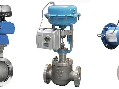
 How to Choose the Right Control Valve for High-Pressure Petrochemical Applications
 The Steel Joints of Coal Chemical Industry: A Complete Guide to How Valves & Instruments Govern the Entire Process Flow
 Why Are Valve Positioners So Important?