
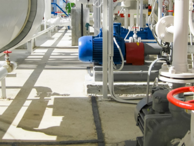
Essential Explosion-Proof Knowledge for Instrumentation You Must Know
Fundamental Principles of Instrument Explosion Protection:
Preventing explosions requires eliminating the simultaneous presence of all three conditions necessary for detonation: ignition source, combustible material, and oxidizer (oxygen). Since oxygen (air) is ubiquitous and difficult to control, the two most common explosion protection principles involve controlling explosive gases and ignition sources. Within the instrumentation industry, another principle exists: controlling the explosion scope.
(1) Controlling Explosive Gases. Artificially creating a space free of explosive gases within hazardous locations (industrial sites where all three conditions for explosion are present are termed hazardous locations), then installing instruments within this space. A typical example is the positive pressure explosion-proof method (Exp). The working principle involves filling a sealed enclosure with clean or inert gas that does not contain explosive gases, maintaining an internal pressure slightly higher than the external atmosphere, and installing the instrument within this enclosure. This method is commonly used for explosion protection in online analytical instruments and for placing computers, PLCs, operator stations, or other instruments in the field within positive-pressure explosion-proof instrument cabinets.
(2) Controlling the Explosion Scope: This method artificially confines an explosion to a limited local area, preventing it from triggering a larger-scale explosion. A typical example is the flameproof enclosure method (Exd). The working principle involves designing an instrument with a sufficiently robust enclosure. All interfaces are rigorously designed, manufactured, and installed according to standards to ensure that any explosion occurring inside the enclosure does not ignite the hazardous gas (explosive gas) outside the enclosure. Design and manufacturing standards for flameproof enclosures are extremely stringent, with equally rigorous installation, wiring, and maintenance procedures. This approach often results in bulky electrical equipment and instruments requiring power shutdown for operation, yet it remains the most effective solution in many scenarios.
(3) Controlling Ignition Sources Artificially eliminating ignition sources involves removing both sparks capable of ignition and surface temperature rises sufficient to cause ignition. The intrinsic safety method (Exi) is a typical example. Its principle: Using safety barrier technology, the electrical energy supplied to field instruments is restricted to a safe range incapable of producing either sparks or surface temperature rises sufficient for ignition. According to international and Chinese national standards, the intrinsically safe explosion-proof method ensures explosion safety in hazardous areas even when any equipment connected to the safe side of the safety barrier malfunctions (voltage not exceeding 250V). Ex ia intrinsically safe equipment will not cause an explosion of an explosive gas mixture under normal operation, during a single fault, or during a double fault. Therefore, this method is the safest and most reliable explosion-proof approach.
Characteristics of Explosion-Proof Instruments and Area Classification:
Gas (CLASS I)
Zone 0: Areas where explosive gas mixtures are present continuously or for long periods under normal conditions.
Zone 1: Areas where explosive gas mixtures may be present under normal conditions.
Zone 2: Areas where explosive gas mixtures are not present under normal conditions but may occur occasionally or for short periods under abnormal conditions.
Dust or Fibers (CLASS II/III)
Locations where explosive dust or combustible fiber mixtures with air may be present continuously, frequently for short periods, or for extended periods under normal conditions are classified as Zone 10.
Locations where explosive dust or combustible fiber mixtures with air cannot be present under normal conditions but may occur occasionally or for short periods under abnormal conditions are classified as Zone 11.
Characteristics of explosion-proof instruments: They bear an explosion-proof marking indicating compliance with specific explosion-proof standards, such as China’s national standards or European explosion-proof standards.
Explosion-proof methods: Flameproof d; Oil-filled o; Increased safety e; Sand-filled q; Intrinsically safe i; Non-sparking n; Pressurized p; Special s.
Explosion-proof measures:
- Isolate existing ignition sources.
- Prevent ignition sources from occurring.
- Limit the energy of ignition sources.
- Separate hazardous substances from ignition sources.
- Prevent ignition sources from occurring.
Stay updated with the latest news and industry insights from GUANYA Petrochemical Equipment Co., Ltd. We share news, project case studies, technical articles, and more!
 The Steel Joints of Coal Chemical Industry: A Complete Guide to How Valves & Instruments Govern the Entire Process Flow
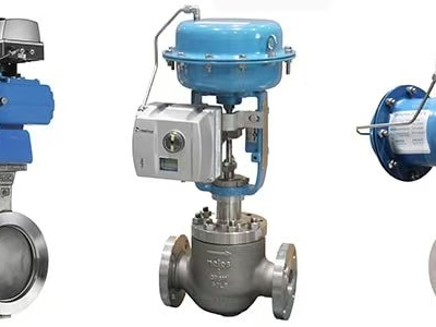 Why Are Valve Positioners So Important?
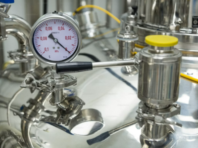 5 Common Causes of Inaccurate Level Gauge Readings and On-Site Troubleshooting Methods
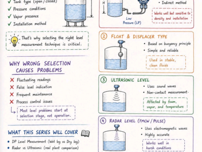 Differential Pressure Level Transmitter: Impulse Line Principle & Troubleshooting