
Complete Guide to Cryogenic Valve Classification, Installation, and Maintenance
I. Introduction to Cryogenic Valves
Cryogenic valves are not merely modified versions of standard valves but specialized equipment designed specifically for cryogenic operating conditions. According to international standards, valves operating below -40°C are classified as cryogenic valves, with those functioning below -100°C designated as deep cryogenic valves.
These valves face challenges far beyond imagination: they handle highly demanding fluids such as liquid oxygen (-183°C), liquid nitrogen (-196°C), and liquefied natural gas (-162°C). These media not only possess extremely low temperatures but also exhibit flammability, explosiveness, high permeability, and phase-change expansion. In the event of a leak, the liquid instantly vaporizes, expanding hundreds of times in volume and potentially causing catastrophic consequences.
II. Classification of Cryogenic Valves
Classified by medium temperature into cryogenic valves and low-temperature valves.
① Low-Temperature Valves: Medium operating temperature -100°C < t < -40°C
② Cryogenic Valves: Medium operating temperature < -100°C
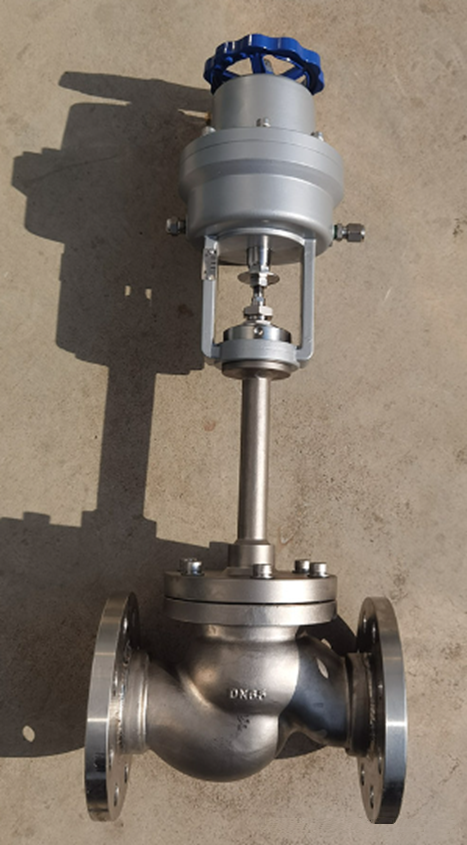
LNG Cryogenic Valves
III. Cryogenic Valve Performance Parameters, Product Specifications, and Design Parameters
① Nominal Pressure: CLASS 150–1500; PN20~250
② Nominal Size DN15~1200
③ Connection Types: Flanged (FF/RF/RJ), Welded (BW), Threaded (NPT), Socket Weld (SW), etc.
④ Valve Materials and Service Temperatures: See table below
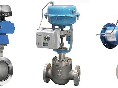
⑤ Actuation Methods: Manual, Bevel Gear Drive, Electric, Pneumatic, Gas-Liquid Interlock, etc.
IV. Special Requirements for Cryogenic Valves
Cryogenic valves operate under severe conditions, handling media that are predominantly flammable, explosive, toxic, and highly permeable. Their minimum temperature can reach -269°C, with maximum operating pressures up to 25MPa. Consequently, their design, manufacturing, and inspection differ significantly from conventional valves. Specific requirements for cryogenic valve design, structure, and material selection are as follows:
1. Design and Structural Requirements
(1) Extended Service Life: Valves and components must maintain long-term operational capability in cryogenic media and environments, typically requiring a 10-year lifespan or 3,500–5,000 opening cycles.
(2) Cryogenic Insulation: Heat influx not only reduces thermal efficiency (if excessive) but also causes rapid vaporization of internal fluids, increasing operational costs. Therefore, cryogenic valves typically employ insulation wrapping below the bonnet neck to prevent medium temperature loss.
(3) Abnormal Pressure Rise Design: For double-seated cryogenic valves, residual cryogenic liquid trapped in the valve cavity after closure gradually absorbs atmospheric heat and vaporizes. The vaporized liquid expands over 600 times in volume. This causes abnormal pressure buildup inside the valve body, posing significant risks to the valve, piping, and equipment. For example, liquefied natural gas (LNG) exists as a liquid at -162°C (pressure 0.2–0.4 MPa). When pressure rises to 20°C, its pressure increases to 29.3 MPa. To prevent abnormal pressure buildup in the intermediate chamber, cryogenic valves should incorporate one of the following structural measures:
① Install a pressure relief hole: Also known as a pressure equalization or vent hole, this involves drilling a small hole on the side of the closing element (e.g., gate, ball) to balance pressure between the valve body cavity and the inlet side. When cavity pressure rises, gas escapes through this hole, equalizing pressure and ensuring safe operation. This simple method is widely adopted. When using pressure relief holes, the valve body must display an arrow indicating fluid flow direction. During installation, ensure the relief hole faces the inlet side of the medium. Particular attention is required when the relief hole is located on the gate or ball.
② Install safety valves and vent lines: Equipping valves with safety valves and vent lines allows discharge of abnormal high pressure. However, ensure discharged media are safely directed or collected.
2. Key Considerations for Selecting Cryogenic Valves:
Temperature Rating: Determine whether cryogenic or deep cryogenic valves are required based on actual operating temperatures.
Pressure Rating: Account for both operating pressure and extreme scenarios of abnormal pressure surges.
Connection Method: Select flanged, welded, threaded, or other connection types according to system requirements.
Actuation Method: Consider operating frequency, automation level, and environmental conditions.
Material Compatibility: Ensure materials are compatible with the medium to prevent chemical reactions.
3. Special Safety Designs:
Fire-Resistant Structure: Maintains sealing integrity during fire incidents
Anti-Static Devices: Prevents static sparks from ball-seat friction
Drip Tray Design: Prevents condensation from infiltrating insulation layers and causing ice buildup
GUANYA Petrochemical Equipment delivers exceptional reliability for your energy and process industries. We specialize in providing comprehensive solutions for the petrochemical, natural gas, LNG, and clean energy sectors—from high-precision automated control valves and smart instrumentation to critical process equipment. Whether integrating systems for new projects or upgrading existing lines with intelligent solutions, our superior products and engineering expertise ensure safe, efficient, and precise control. Contact us today for a customized solution.
 The Steel Joints of Coal Chemical Industry: A Complete Guide to How Valves & Instruments Govern the Entire Process Flow
 Why Are Valve Positioners So Important?
 5 Common Causes of Inaccurate Level Gauge Readings and On-Site Troubleshooting Methods
 Differential Pressure Level Transmitter: Impulse Line Principle & Troubleshooting