
Unstable Control of Control Valves? Check These 5 Key Points of Valve Positioners First
In industrial sites such as petrochemical, chemical, power generation, and new energy industries, control valves serve as the “actuators” of process control and directly determine the stability of process parameters. Engineers often encounter problems including frequent fluctuations in temperature, pressure and flow, valve oscillation, control lag, and large setpoint deviations. While they tend to prioritize troubleshooting process conditions and valve bodies, they usually overlook the core control component — the valve positioner.
Most unstable control faults of control valves stem from abnormal positioner operation rather than spool wear or medium abnormalities. As the “brain” of a control valve, the positioner receives control system signals and accurately matches the valve travel. Abnormal working condition adaptation, parameter deviation, or component aging will directly lead to control failure.
Selecting a control valve with a reliable positioner design from the outset can significantly reduce the frequency of these instability issues down the line. For engineers evaluating or replacing control valves for petrochemical, power generation, or new energy applications, browsing a range of industrial control valves with documented positioner compatibility and material specifications is a useful first step before troubleshooting begins.
On-site troubleshooting does not require blind disassembly or repeated commissioning. This article summarizes five core troubleshooting key points for positioner-induced control instability, covering more than 90% of common regulation fluctuation faults, enabling junior engineers to quickly and accurately locate problems.
Key Point 1: Check the Air Supply — 80% of Control Fluctuations Stem from Unqualified Air Supply
Most engineers prefer to check electrical and calibration parameters first, ignoring the fundamental air supply condition. For pneumatic and smart valve positioners, clean, dry and stabilized air supply is the prerequisite for precise control. Accurate parameter calibration is meaningless if the air supply fails to meet standards.
Common Fault Phenomena: Frequent small-amplitude valve oscillation, inconsistent response speed, recurring steady-state deviation drift, and extremely unstable control at low valve openings.
Core Troubleshooting Points:
- Mismatched air supply pressure: Insufficient pressure causes insufficient actuator thrust and control lag; excessive pressure leads to overload of the pneumatic circuit and overtravel oscillation. The air supply pressure must be adjusted to the rated standard range in accordance with the equipment nameplate.
- Oil, water and impurities in air supply: Unpurified compressed air with moisture, oil stains and dust will block positioner nozzles, baffles and orifices, resulting in unsmooth pneumatic transmission and delayed pressure response, which directly causes control fluctuations. This is the leading cause of frequent positioner faults in dusty and humid working conditions.
- Failed pressure reducing valve: A degraded front-mounted pressure reducing valve cannot maintain stable pressure, leading to fluctuating input pressure of the positioner with the start-stop of air compressors and unstable valve opening.
Solutions: Regularly drain accumulated water and clean filter element impurities; replace failed pressure reducing valves to ensure stable and clean air supply; install multi-stage filtration and drying devices for harsh working conditions to eliminate air supply faults at the source.
Key Point 2: Inspect the Feedback Mechanism — Travel Deviation Is the Main Cause of Control Errors
The core working logic of a positioner is “receiving commands → comparing actual travel → dynamic deviation correction”, and the feedback mechanism acts as the “eyes” of the positioner. Distorted feedback signals will trigger continuous incorrect correction, directly causing valve overshoot, large hysteresis and unstable regulation.
Common Fault Phenomena: Recurring small swing after valve positioning, constant deviation between setpoint and actual value, no response to small control signals, and severe overshoot under large signals.
Core Troubleshooting Points:
- Loose feedback linkage and excessive clearance: Long-term equipment vibration loosens linkage screws and causes wear and backlash at hinge joints, leading to delayed and distorted travel feedback and continuous incorrect regulation by the positioner.
- Deviated installation angle of feedback lever: Linear and rotary valve feedback arms have standard installation angles. Excessive offset deteriorates the linearity of travel collection and greatly reduces control accuracy in the middle opening range.
- Stuck and corroded feedback components: In outdoor, corrosive and dusty environments, feedback rotating shafts are prone to dust accumulation and corrosion, resulting in unsmooth rotation, blocked travel feedback and control oscillation.
Solutions: Fasten feedback linkage screws to eliminate mechanical clearance; recalibrate the feedback arm installation angle to ensure full-stroke linear matching; clean and lubricate feedback rotating shafts, replace severely corroded parts promptly, and finally perform automatic recalibration.
Key Point 3: Verify Calibration Parameters — Blind Calibration Is a Major Cause of Man-Made Faults
Faced with unstable control, most on-site personnel directly perform automatic recalibration. However, inappropriate calibration parameters and incorrect calibration scenarios will aggravate control disorder. The sensitivity, response speed and damping parameters of smart positioners must match actual valve working conditions and medium characteristics.
Common Fault Phenomena: Oscillation during valve start-stop, fine adjustment jitter, control instability under variable loads, and frequent automatic calibration failures.
Core Troubleshooting Points:
- Excessively low damping parameters: Insufficient damping leads to over-sensitive positioner response, which is susceptible to minor process and air supply fluctuations and causes high-frequency oscillation; excessive damping will result in control lag and slow response.
- Unmatched valve load characteristics: Small-caliber and low-pressure-differential light-load valves do not require high gain parameters, which will cause overshoot and oscillation; insufficient gain for heavy-load valves with large friction will lead to inadequate regulation and residual deviation.
- Forced calibration under process load: On-site calibration requires smooth valve operation and stable medium conditions. Calibration under pressure, load or fluctuating medium conditions will collect wrong travel data and cause full-range control inaccuracy.
Solutions: Appropriately increase damping and reduce gain for light-load valves to avoid oscillation; moderately improve response parameters for heavy-load valves to eliminate control lag; prioritize no-load calibration during shutdown. If on-site calibration is necessary under operating conditions, stabilize process parameters in advance.
Key Point 4: Check Pneumatic Circuit Leakage and Blockage — Most Easily Overlooked Hidden Faults
Different from obvious air leakage faults, micro-leakage and partial blockage are hidden faults that will not cause direct valve failure but lead to persistent unstable control and excessive steady-state deviation, with high troubleshooting difficulty.
Common Fault Phenomena: Poor valve position retention, slight travel drop, unstable low-opening operation and long-term small-amplitude fluctuation.
Core Troubleshooting Points:
- Slight nozzle-baffle blockage: Dust and oil deposits on nozzles change pneumatic back pressure, resulting in unstable pressure transmission, which is a top cause of inaccurate fine adjustment of smart positioners.
- Aging and micro-leakage of amplifier diaphragms: Long-term operation causes aging and deformation of sealing diaphragms, leading to micro air leakage, reduced pressure retention capacity and inaccurate valve positioning.
- Leakage of pneumatic joints and sealing rings: Vibration and high-temperature aging damage sealing performance, causing uneven pressure relief in pneumatic circuits. The positioner needs continuous air supply for correction, resulting in valve oscillation and fluctuation.
Solutions: Regularly purge nozzles and orifices to remove dust and oil deposits; check the tightness of pneumatic joints and replace aging sealing rings and diaphragms; optimize the air supply purification system and strengthen equipment protection for dusty and oily working conditions.
Key Point 5: Adapt to Working Conditions — Continuous Control Deviations Caused by Temperature, Vibration and Corrosion
Complex industrial conditions including extreme temperature, continuous vibration and salt spray corrosion will continuously affect the electrical and mechanical performance of positioners, causing parameter drift and inaccuracy. Such persistent and recurring faults are often misjudged as valve body failures.
Common Fault Phenomena: Control accuracy fluctuation with day-night temperature difference, increased deviation under equipment vibration, unstable operation in rainy outdoor environments, and sluggish valve response at low temperatures.
Core Troubleshooting Points:
- Temperature drift: Extreme high and low temperatures cause electrical parameter offset and spring stiffness variation of positioners, resulting in zero drift, range inaccuracy and control deviation.
- Vibration interference: Vibration from pumps and pipelines loosens internal positioner components and jitters feedback signals, triggering continuous small-amplitude valve oscillation.
- Invasion of corrosion and dust: Salt spray, sulfide gas and dust erode precision internal components, causing mechanical jamming, poor electrical contact and declining control stability.
Solutions: Install heat-insulating brackets and shields for high-temperature working conditions to avoid direct heat exposure; reinforce mounting brackets and add shock absorption structures for vibrating environments; select positioners with corresponding explosion-proof and anti-corrosion high-protection grades for corrosive and dusty outdoor conditions, and conduct regular condition adaptation verification and parameter calibration.
Summary: Accurate Troubleshooting Avoids Blind Operation and Maintenance
Unstable control of control valves does not always mean valve failure, but mostly positioner maladjustment. On-site maintenance personnel can quickly locate more than 90% of fluctuation, oscillation and deviation faults by following the troubleshooting sequence: air supply → feedback mechanism → calibration parameters → pneumatic circuit status → working condition adaptation, without blind disassembly and replacement.
As the core control component of control valves, positioners require accurate condition adaptation, standardized calibration and regular hidden danger investigation. These measures are far more effective in ensuring process stability and reducing operation and maintenance costs than frequent repairs and replacements.
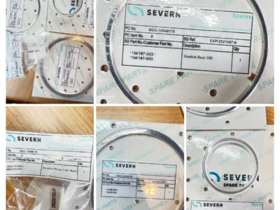 Successfully Supplied SEVERN GLOCON Control Valve & Actuator Repair Kits for CNOOC Platform 19-6
 Domestic Valves in Industrial Applications: A Practical Sourcing Guide for Global Buyers
 How Triple‑Eccentric Butterfly Valves Achieve High‑Performance Modulation
 How to Choose an Industrial Instrument Supplier? A Complete Guide from Selection to Service